G403
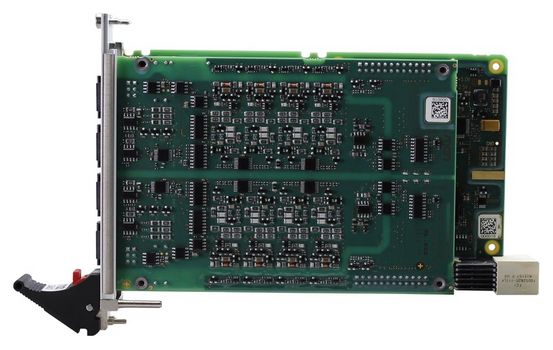
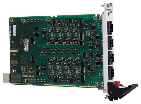
Railway I/O Board for Digital I/O
Hauptmerkmale
- 4HP PICMG CPCI-S.0 CompactPCI Serial (PCIe 1.0)
- 16 bidirectional digital I/Os
- Organized in 4 optically isolated groups
- Connected via spring cage terminal blocks
- Flexible I/O configuration
- Individual edge-triggered interrupts
- I/O voltage range 14.4 VDC to 154 VDC
- Current output 1 A at 24 V
- Driver support for all common operating systems
- -40 °C to +85 °C
- EN 50155 compliant
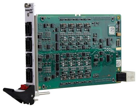
Digital I/O for Railway
The G403 is a digital I/O CompactPCI Serial board especially designed for railway applications. The card is used for input/output of digital signals with different voltage levels and ground references. It supports 16 bidirectional binary input/output channels, which are separated into four optically isolated groups.
EN 50155 Compliance
Its voltage range from 14.4 VDC to 154 VDC and its current output of 1 A at 24 V complies with EN 50155, which makes the board ready for immediate use in train applications.
Safety Measures for Mobile Environments
The four front connectors are implemented by using spring cage terminal blocks causing only low wiring outlay and supporting fast installation. The digital railway I/O supports all safety measures necessary for mobile environments like trains including voltage and temperature supervision and readback of outputs.
- 16 digital signals
- 4 optically isolated groups
- 4 channels for each group
- The following I/O configurations are possible:
- 16 inputs/16 outputs
- Each channel is runtime configurable as input or output
- Individual edge-triggered interrupts
- High-side output switches
- High output current: max. 1 A per channel at 24 V
- Temperature and voltage supervision
- Output voltage range
- Limits continuous: 0 VDC to +138 VDC
- Limits (duration <1s): 0 VDC to +154 VDC
- Switching time for output change: 400 µs (rise time)/600 µs (fall time)
- Input voltage range
- Limits continuous: -0.7 VDC to +138 VDC
- Limits (duration <1s): -0.7 VDC to +154 VDC
- Input voltage of external supply voltage
- Can be configured individually for each group
- Nominal: +24 VDC to +110 VDC
- Limits continuous: +16.8 VDC to +138 VDC
- Limits (duration <1s): +14.4 VDC to +154 VDC
- Switching threshold: 40% (+15%/-15%) of external supply voltage
- Compliance with CompactPCI Serial PICMG CPCI-S.0 Specification
- Peripheral slot
- P1 connector with geographical addressing for distinguishing boards in a system with several boards
- Supply voltage: +12V (9.5 to 15.5 V)
- Power consumption: 5 W max.
- Isolation voltage:
- 1500 VAC between isolated side and digital side
- 1500 VAC between the channels
- Dimensions: 3U, 4 HP
- Weight: approx. 285 g
- Cooling
- Air cooling, airflow 1.0 m/s
- Compliance level: This product is prepared for use in EN 50155 systems. Some parameters are system-dependent and are specified on system level.
- Operating temperature: -40 °C to +85 °C (EN 50155:2021, Tmax/PCB = +85 °C; designed for use in OT4+ST2 systems)
- Equipment location
- EN 50155:2021, location 1, closed electrical operating area
- EN 50155:2021, location 2, cabin and interiors
- Rapid temperature variations: EN 50155:2021, class H1, no requirements
- Storage temperature: -40 °C (EN 50155:2021) to +85 °C (EN 60068-2-2, Bb)
- Altitude: +2000 m max. (EN 50125-1:2014, class AX)
- Pollution degree: EN 50124-1:2017, class PD2
- Shock: 30 ms @ 50 m/s² (EN 61373:2010/AC:2017-09, vehicle body, cat. 1, class B)
- Vibration: 10 min @ 1.01 m/s² (functional) and 5 h @ 5.72 m/s² (long-life) (EN 61373:2010/AC:2017-09, vehicle body, cat. 1, class B)
- Power supply: General compliance with power supply requirements of EN 50155:2021
- Electrical safety
- EN 50155:2021
- EN 62368-1:2016
- Fire protection: EN 45545-2:2020, EL9, HL3
- EMC emission: EN 50121-3-2:2016 + A1:2019
- EMC immunity: EN 50121-3-2:2016 + A1:2019
- Protective coatings: EN 50155:2021, class PC2 (Any PCB protected on both sides)
- Useful life: 10 years (EN 50155:2021, class L2)
- Standard OS UART drivers
- Demo application for Linux, Windows, VxWorks